Let us now see the
basics of what we talked about in the first post about VRFs - in action. We'll
start with an extremely small topology consisting of two Cisco routers - one
running legacy IOS, the other running IOS XR - and see how we could implement "the
litest" VRF-lite to segment the L3 topology into two domains.
Our task here is:
- Create one L3 instance for "user" traffic, where subnets on R1 should be reachable from subnets on XR2 and vice versa,
- Create another L3 instance for "server" traffic (whatever that might be), where only server subnets should be able to reach each other on both routers.
The starting
addressing scheme is as follows:
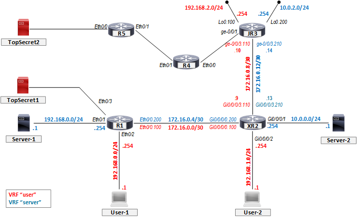
- One "user" subnet which is connected to R1 is 192.168.0.0/24, with .254 being the Eth0/2 interfaca address (and default gateway for hosts there)
- One "server" subnet, which is using the exact same subnet and interface address as the first one 192.168.0.0/24 (and .254 on the R1 Eth0/1 interface)
- Other "user" subnet on XR2 - 192.168.1.0/24 (.254 on the router interface Gi0/0/0/2)
- Other "server" subnet ont XR2 - 10.0.0.0/24 (.254 on the router interface Gi0/0/0/1)
We can start first
with subnet-to-subnet connectivity, and we'll move on later to additional
connectivity requests as we go along.

First, let's make
sure we don't have any VRFs configured:
R1#sh ip
  vrf
R1# |
Great,
nothing there. Let's now configure a VRF, and we'll use the "newer"
IOS syntax with the command "vrf
definition":
R1#conf tR1(config)#vrf
definition userR1(config-vrf)#address-family
ipv4R1(config-vrf-af)#endR1# |
And
that's about it. We created a separate routing instance, gave it a name "user",
and specified that it is to be used for forwarding IPv4 unicast traffic.
Let's see what IOS
has created for us:
R1#sh vrf
  detail user
VRF user
(VRF Id = 1); default RD <not set>; default VPNID <not set> New
CLI format, supports multiple address-families
Flags: 0x1808 No
interfacesAddress
family ipv4 (Table ID = 1 (0x1)):
Flags: 0x0 No
Export VPN route-target communities No
Import VPN route-target communities No
import route-map No
global export route-map No
export route-map VRF
label distribution protocol: not configured VRF
label allocation mode: per-prefixAddress
family ipv6 not activeR1# |
Great, we can see
that there is something called "Table ID" which is our identifier
describing the new entity we created. Let's now try and interface Eth0/2, and
we'll check if the new routing table is populated as we expect in the list
above:
R1(config)#interface
  e0/2
R1(config-if)#vrf
forwarding userR1(config-if)#ip
address 192.168.0.254 255.255.255.0R1(config-if)#no
shutR1(config-if)#R1#*Oct
5 10:53:57.141: %LINK-3-UPDOWN: Interface Ethernet0/2, changed state to upR1#*Oct
5 10:53:57.718: %SYS-5-CONFIG_I: Configured from console by console*Oct
5 10:53:58.146: %LINEPROTO-5-UPDOWN: Line protocol on Interface Ethernet0/2,
changed state to upR1# |
Mkay, we got an
"up/up" interface, so we expect that the prefixes 192.168.0.254/32
(local) and 192.168.0.0/24 (connected) should be installed in the routing table
for VRF A. Let's check and verify first that these prefixes were not inserted
in the "global" routing table (the one that comes out of the box and
is not tied to any VRFs):
R1#show ip
  route
Codes: L -
local, C - connected, S - static, R - RIP, M - mobile, B - BGP
D - EIGRP, EX - EIGRP external, O - OSPF, IA - OSPF inter area
N1 - OSPF NSSA external type 1, N2 - OSPF NSSA external type 2
E1 - OSPF external type 1, E2 - OSPF external type 2
i - IS-IS, su - IS-IS summary, L1 - IS-IS level-1, L2 - IS-IS level-2
ia - IS-IS inter area, * - candidate default, U - per-user static route
o - ODR, P - periodic downloaded static route, H - NHRP, l - LISP
a - application route
+ - replicated route, % - next hop overrideGateway of
last resort is not setR1# |
Yup, this one is
empty as expected. So far - so good. Let's display the routing table
corresponding to VRF "user", since our prefixes should be installed
there:
R1#show ip
route vrf userRouting
Table: userCodes: L -
local, C - connected, S - static, R - RIP, M - mobile, B - BGP
D - EIGRP, EX - EIGRP external, O - OSPF, IA - OSPF inter area
N1 - OSPF NSSA external type 1, N2 - OSPF NSSA external type 2
E1 - OSPF external type 1, E2 - OSPF external type 2
i - IS-IS, su - IS-IS summary, L1 - IS-IS level-1, L2 - IS-IS level-2
ia - IS-IS inter area, * - candidate default, U - per-user static route
o - ODR, P - periodic downloaded static route, H - NHRP, l - LISP
a - application route
+ - replicated route, % - next hop overrideGateway of
last resort is not set
192.168.0.0/24 is variably subnetted, 2 subnets, 2 masksC
192.168.0.0/24 is directly connected, Ethernet0/2L
192.168.0.254/32 is directly connected, Ethernet0/2R1# |
There we are. It's
there. This networking stuff is easy, can't see what the fuss is all about.
Let's configure the
server VRF and the corresponding interface Eth0/1:
R1(config)#vrf
definition serverR1(config-vrf)#address-family
ipv4R1(config-vrf-af)#exitR1(config-vrf)#interface
e0/1R1(config-if)#ip
address 192.168.0.254 255.255.255.0R1(config-if)#no
shutR1(config-if)#endR1#*Oct 8 15:09:34.290: %SYS-5-CONFIG_I: Configured
from console by consoleR1#*Oct 8 15:09:34.334: %LINK-3-UPDOWN: Interface
Ethernet0/1, changed state to up*Oct 8 15:09:35.339: %LINEPROTO-5-UPDOWN: Line
protocol on Interface Ethernet0/1, changed state to upR1# |
Good. No, wait. We
forgot to add the interface to the new VRF. Darn. Let's do that now:
R1(config)#interface
e0/1R1(config-if)#vrf
forwarding server% Interface
Ethernet0/1 IPv4 disabled and address(es) removed due to enabling VRF serverR1(config-if)#do
show run interface e0/1Building
configuration...Current
configuration : 67 bytes!interface
Ethernet0/1 vrf forwarding server no ip addressendR1(config-if)#ip
address 192.168.0.254 255.255.255.0R1(config-if)#endR1# |
Whoa, look at that.
Moving the interface from one VRF to another (or from a "global" VRF
to VRF user in this case) caused IOS to remove the configured IP address. Well,
this does make sense, since the IP addresses make sense only in the context of
VRF in which they're configured. So, once we re-applied the address we should
be good to go. Our device now allows us to have overlapping address space (and
even overlapping interface addresses!) - we have 192.168.0.254/24 configured on
Eth0/1 and Eth0/2, but since those are in different VRFs - the router has no
problem differentiating between the two. How cool is that… [1]
Let us now test our
static routes - we'll try and add a couple of "dummy" static routes
in both VRFs, just to see if they'll behave as we expect them to. We'll remove
them after we're done, because we won't need them later.
R1(config)#ip
route vrf server 172.20.1.0 255.255.255.0 192.168.0.1 name Dummy_routeR1(config)#endR1#sh ip
route vrf serverRouting
Table: server[...output
truncated...]Gateway of
last resort is not set 172.20.0.0/24 is subnetted, 1 subnetsS 172.20.1.0 [1/0] via 192.168.0.1 192.168.0.0/24 is variably subnetted, 2
subnets, 2 masksC 192.168.0.0/24 is directly connected,
Ethernet0/1L 192.168.0.254/32 is directly
connected, Ethernet0/1R1# |
There it is. Onward
and upward! I like it! Another!
R1(config)#ip
route vrf server 172.20.2.0 255.255.255.0 172.16.1.1 name Another_dummy_routeR1(config)#endR1#sh ip
route*Oct 8 15:23:39.219: %SYS-5-CONFIG_I: Configured
from console by consoleuR1#sh ip
route vrf serverRouting
Table: server[...output
truncated...]Gateway of
last resort is not set 172.20.0.0/24 is subnetted, 1 subnetsS 172.20.1.0 [1/0] via 192.168.0.1 192.168.0.0/24 is variably subnetted, 2
subnets, 2 masksC 192.168.0.0/24 is directly connected,
Ethernet0/1L 192.168.0.254/32 is directly
connected, Ethernet0/1R1# |
Wow, these guys are
good. The router cannot resolve which outgoing interface the configured next
hop address maps to (we have no route for 172.16.1.1), so this static route
isn't installed in the routing table. Everything's working as expected. (Mind
you, I've now quietly removed those static routes since we won't be needing
them anymore, so they won't show up in configs or routing tables anymore. Don’t
go looking for them. Don't make it weird.)
Let's move on to XR2
and do the same - configure two VRFs and their interfaces, and put the
addressing in place. Also, we'll note the slight syntactic difference between
legacy IOS and IOS-XR:
RP/0/0/CPU0:XR2(config)#vrf
userRP/0/0/CPU0:XR2(config-vrf)#address-family
ipv4 unicastRP/0/0/CPU0:XR2(config-vrf-af)#exitRP/0/0/CPU0:XR2(config-vrf)#exitRP/0/0/CPU0:XR2(config)#commitMon
Oct 8 15:34:21.749 UTCRP/0/0/CPU0:XR2(config)#vrf
serverRP/0/0/CPU0:XR2(config-vrf)#address-family
ipv4 unicastRP/0/0/CPU0:XR2(config-vrf-af)#exitRP/0/0/CPU0:XR2(config-vrf)#exitRP/0/0/CPU0:XR2(config)#commitMon
Oct 8 15:34:34.008 UTCRP/0/0/CPU0:XR2(config)#interface
Gi0/0/0/1
RP/0/0/CPU0:XR2(config-if)#vrf
server
RP/0/0/CPU0:XR2(config-if)#ip
address 10.0.0.254 255.255.255.0
RP/0/0/CPU0:XR2(config-if)#no
shut
RP/0/0/CPU0:XR2(config-if)#commit
Mon Oct 8 15:40:06.165 UTC
RP/0/0/CPU0:XR2(config-if)#interface
gi0/0/0/2
RP/0/0/CPU0:XR2(config-if)#vrf
user
RP/0/0/CPU0:XR2(config-if)#ip
address 192.168.1.254 255.255.255.0
RP/0/0/CPU0:XR2(config-if)#no
shut
RP/0/0/CPU0:XR2(config-if)#commit
Mon Oct 8 15:40:25.024 UTC
RP/0/0/CPU0:XR2(config-if)#end
RP/0/0/CPU0:XR2#
|
In the words of
great John Oliver: "Cool." [2]
Let's do a quick check if we've addressed everything the way we should:
RP/0/0/CPU0:XR2#sh
ip int brMon
Oct 8 15:40:32.814 UTCInterface IP-Address Status ProtocolMgmtEth0/0/CPU0/0 unassigned Up UpGigabitEthernet0/0/0/0 unassigned Up UpGigabitEthernet0/0/0/3 unassigned Up UpRP/0/0/CPU0:XR2# |
What in tarnation..?
Where are the two interfaces we just configured? Why aren't they displayed?
Well, "ackshually", IOS-XR is just a bit more consistent with VRFs
than plain old IOS. Not only we need to specify the VRF when we're trying to
display the routes, we also need to specify it if we "just" want to
check the interface IP addresses. So, let's do that:
RP/0/0/CPU0:XR2#show
ip vrf all interface briefMon
Oct 8 15:46:02.461 UTCInterface IP-Address Status Protocol Vrf-NameMgmtEth0/0/CPU0/0 unassigned Up Up defaultGigabitEthernet0/0/0/0 unassigned Up Up defaultGigabitEthernet0/0/0/1 10.0.0.254 Up Up serverGigabitEthernet0/0/0/2 192.168.1.254 Up Up userGigabitEthernet0/0/0/3 unassigned Up Up default |
Ah, there they are,
much better. So - now we have two routers, running two separate routing
instances on them, but they're kinda… Disconnected. Hosts connected to R1
cannot really communicate to hosts on XR2, not even in their own routing
domain. While this is a quite secure solution [3],
we'll definitely need to configure something to allow them to communicate. So
let's do that using OSPF.
To allow VRF
"server" hosts to communicate across the two routers, we'll run a
single area (area 0) OSPF between R1 and XR2 to first exchange routing
information about the connected subnets. But since we'll need to run the same
setup for the other VRF "user" (consistency is a good design
principle [4]), we'll have to think
hard about how are we going to accomplish that. The thing is - to run a routing
protocol "in a VRF" - especially OSPF, where we enable it on a
per-interface basis - we need to think in which VRF are we going to place the interfaces
over which we intend to peer the two routers.
Since we only have
one physical Ethernet link between the two routers, if we add the
"whole" link with the (the physical interfaces on each link end) to
the VRF "server" - we'll have to run another physical connection
between R1 and XR2 to bring up OSPF peering for VRF "user". But I did
say we can add logical L3 interfaces into VRFs, so - VLANs to the rescue: we'll
create two 802.1q tagged subinterfaces on the link between R1 and XR2, and
place them into appropriate VRF, and we'll address them as follows:
R1
|
XR2
|
||
VLAN ID
|
VRF
|
Eth0/0.VLANID
|
Gi0/0/0/0.VLANID
|
100
|
user
|
172.16.0.1/30
|
172.16.0.2/30
|
200
|
server
|
172.16.0.5/30
|
172.16.0.6/30
|
Let's configure R1
side:
R1(config)#interface
e0/0R1(config-if)#no
shutR1(config-if)#interface
e0/0.100*Oct 8 16:12:15.569: %LINK-3-UPDOWN: Interface
Ethernet0/0, changed state to up*Oct 8 16:12:16.578: %LINEPROTO-5-UPDOWN: Line
protocol on Interface Ethernet0/0, changed state to upR1(config-if)#interface
e0/0.100R1(config-subif)#vrf
forwarding userR1(config-subif)#encapsulation
dot1q 100R1(config-subif)#ip
address 172.16.0.1 255.255.255.252R1(config-subif)#no
shutR1(config-subif)#int
e0/0.200R1(config-subif)#vrf
forwarding serverR1(config-subif)#encapsulation
dot1q 200R1(config-subif)#ip
address 172.16.0.5 255.255.255.252R1(config-subif)#no
shutR1(config-subif)#endR1# |
Now XR2:
RP/0/0/CPU0:XR2(config)#int
gi0/0/0/0RP/0/0/CPU0:XR2(config-if)#no
shutRP/0/0/CPU0:XR2(config-if)#exitRP/0/0/CPU0:XR2(config)#commitMon
Oct 8 16:14:15.205 UTCRP/0/0/CPU0:XR2(config)#interface
gi0/0/0/0.100RP/0/0/CPU0:XR2(config-subif)#encapsulation
dot1q 100RP/0/0/CPU0:XR2(config-subif)#vrf
userRP/0/0/CPU0:XR2(config-subif)#ip
address 172.16.0.2 255.255.255.252RP/0/0/CPU0:XR2(config-subif)#no
shutRP/0/0/CPU0:XR2(config-subif)#commitMon
Oct 8 16:14:42.863 UTCRP/0/0/CPU0:XR2(config-subif)#exRP/0/0/CPU0:XR2(config)#interface
gi0/0/0/0.200RP/0/0/CPU0:XR2(config-subif)#encapsulation
dot1q 200RP/0/0/CPU0:XR2(config-subif)#vrf
serverRP/0/0/CPU0:XR2(config-subif)#ip
address 172.16.0.6 255.255.255.252RP/0/0/CPU0:XR2(config-subif)#no
shutRP/0/0/CPU0:XR2(config-subif)#commitMon
Oct 8 16:15:12.011 UTCRP/0/0/CPU0:XR2(config-subif)#endRP/0/0/CPU0:XR2# |
Let's check the
connectivity:
RP/0/0/CPU0:XR2#ping
172.16.0.1 so gi0/0/0/0.100Mon
Oct 8 16:18:25.468 UTCType escape
sequence to abort.Sending 5,
100-byte ICMP Echos to 172.16.0.1, timeout is 2 seconds:.....Success
rate is 0 percent (0/5)RP/0/0/CPU0:XR2#ping
172.16.0.1 so gi0/0/0/0.200Mon
Oct 8 16:18:50.826 UTCType escape
sequence to abort.Sending 5,
100-byte ICMP Echos to 172.16.0.1, timeout is 2 seconds:.....Success
rate is 0 percent (0/5)RP/0/0/CPU0:XR2# |
Hmmm, did we
misconfigure something..? Duh, no, it's just we can't check it like that - ping
is now also VRF-aware! (and tracert as well). Let's do it properly now:
RP/0/0/CPU0:XR2#ping
vrf user 172.16.0.1Mon
Oct 8 16:25:30.230 UTCType escape
sequence to abort.Sending 5,
100-byte ICMP Echos to 172.16.0.1, timeout is 2 seconds:!!!!!Success
rate is 100 percent (5/5), round-trip min/avg/max = 1/4/9 msRP/0/0/CPU0:XR2#ping
vrf server 172.16.0.5Mon
Oct 8 16:25:38.839 UTCType escape
sequence to abort.Sending 5,
100-byte ICMP Echos to 172.16.0.5, timeout is 2 seconds:!!!!!Success
rate is 100 percent (5/5), round-trip min/avg/max = 1/1/1 msRP/0/0/CPU0:XR2# |
Muuuuch better now.
So, now on to OSPF. Let's start with VRF "user" and let's say we're
gonna have OSPF process 12, area 0. We'll enable the following interfaces:
- R1:
- Eth0/2 - passive
- Eth0/0.100 - point-to-point network type
- XR2:
- Gi0/0/0/2 - passive
- Gi0/0/0/0.100 - point-to-point network type
So, R1 config:
R1(config)#interface
e0/0.100R1(config-subif)#ip
ospf network point-to-pointR1(config-subif)#exitR1(config)#router
ospf 12 vrf userR1(config-router)#network
172.16.0.1 0.0.0.0 area 0R1(config-router)#network
192.168.0.254 0.0.0.0 area 0R1(config-router)#passive-interface
ethernet 0/2R1(config-router)#endR1# |
XR2 config:
RP/0/0/CPU0:XR2(config)#router
ospf 12 vrf userRP/0/0/CPU0:XR2(config-ospf-vrf)#area
0RP/0/0/CPU0:XR2(config-ospf-vrf-ar)#interface
Gi0/0/0/0.100RP/0/0/CPU0:XR2(config-ospf-vrf-ar-if)#network
point-to-pointRP/0/0/CPU0:XR2(config-ospf-vrf-ar-if)#exitRP/0/0/CPU0:XR2(config-ospf-vrf-ar)#interface
Gi0/0/0/2RP/0/0/CPU0:XR2(config-ospf-vrf-ar-if)#passiveRP/0/0/CPU0:XR2(config-ospf-vrf-ar-if)#exitRP/0/0/CPU0:XR2(config-ospf-vrf-ar)#exitRP/0/0/CPU0:XR2(config-ospf-vrf)#exitRP/0/0/CPU0:XR2(config-ospf)#exitRP/0/0/CPU0:XR2(config)#commitMon
Oct 8 16:28:34.646 UTCRP/0/0/CPU0:XR2(config)# |
Fingers crossed!
R1#*Oct 8 16:28:40.245: %OSPF-5-ADJCHG: Process 12,
Nbr 192.168.1.254 on Ethernet0/0.100 from LOADING to FULL, Loading DoneR1# |
That's what I like
to see. Let's check out the routing table(s):
R1#show ip
route vrf userRouting
Table: user[...output
truncated...]Gateway of
last resort is not set 172.16.0.0/16 is variably subnetted, 2
subnets, 2 masksC 172.16.0.0/30 is directly connected,
Ethernet0/0.100L 172.16.0.1/32 is directly connected,
Ethernet0/0.100 192.168.0.0/24 is variably subnetted, 2
subnets, 2 masksC 192.168.0.0/24 is directly connected,
Ethernet0/2L 192.168.0.254/32 is directly
connected, Ethernet0/2O 192.168.1.0/24 [110/11] via 172.16.0.2,
00:02:36, Ethernet0/0.100R1# |
And on XR2:
RP/0/0/CPU0:XR2#show
route vrf user
Mon Oct 8 16:33:13.467 UTC
[...output
truncated...]
Gateway of
  last resort is not set
C 172.16.0.0/30 is directly connected,
00:18:30, GigabitEthernet0/0/0/0.100
L 172.16.0.2/32 is directly connected,
00:18:30, GigabitEthernet0/0/0/0.100
O 192.168.0.0/24 [110/11] via 172.16.0.1,
00:04:34, GigabitEthernet0/0/0/0.100
C 192.168.1.0/24 is directly connected,
00:52:48, GigabitEthernet0/0/0/2
L 192.168.1.254/32 is directly connected,
00:52:48, GigabitEthernet0/0/0/2
|
Let's check what the
users say:
User-1>
ping 192.168.1.184 bytes
from 192.168.1.1 icmp_seq=1 ttl=62 time=30.148 ms84 bytes
from 192.168.1.1 icmp_seq=2 ttl=62 time=7.792 ms84 bytes
from 192.168.1.1 icmp_seq=3 ttl=62 time=4.791 ms84 bytes
from 192.168.1.1 icmp_seq=4 ttl=62 time=6.828 ms84 bytes
from 192.168.1.1 icmp_seq=5 ttl=62 time=4.776 msUser-1> |
The users on each
router can communicate! Let's do the same for VRF "server". The
gameplan is the same, OSPF process 12, area 0, on following interfaces:
- R1:
- Eth0/1 - passive
- Eth0/0.200 - point-to-point network type
- XR2:
- Gi0/0/0/1 - passive
- Gi0/0/0/0.200 - point-to-point network type
Let's configure it:
R1(config)#router
ospf 12 vrf server%VRF
specified does not match existing routerR1(config)# |
Uh-oh, thwarted by
IOS at the first step… Could we perhaps change the process ID..? Let's try:
R1(config)#int
e0/0.200R1(config-subif)#ip
ospf network point-to-pointR1(config-subif)#exitR1(config)#router
ospf 22 vrf serverR1(config-router)#passive-interface
e0/1R1(config-router)#network
192.168.0.254 0.0.0.0 area 0R1(config-router)#network
172.16.0.5 0.0.0.0 area 0R1(config-router)#endR1# |
Yup, that works. Now
the other side. But… I'm curious - will XR2 let us have the same process ID?
Let's try:
RP/0/0/CPU0:XR2(config)#router
ospf 12RP/0/0/CPU0:XR2(config-ospf)#vrf
serverRP/0/0/CPU0:XR2(config-ospf-vrf)#commitMon
Oct 8 17:11:54.868 UTCRP/0/0/CPU0:XR2(config-ospf-vrf)# |
Yeah, XR isn't so
picky. And it has a prettier syntax which makes it clear where the process is
running. Let's continue:
RP/0/0/CPU0:XR2(config-ospf-vrf)#area
  0
RP/0/0/CPU0:XR2(config-ospf-vrf-ar)#interface
GigabitEthernet0/0/0/0.200RP/0/0/CPU0:XR2(config-ospf-vrf-ar-if)#network
point-to-pointRP/0/0/CPU0:XR2(config-ospf-vrf-ar-if)#exitRP/0/0/CPU0:XR2(config-ospf-vrf-ar)#interface
GigabitEthernet0/0/0/1RP/0/0/CPU0:XR2(config-ospf-vrf-ar-if)#passive
enableRP/0/0/CPU0:XR2(config-ospf-vrf-ar-if)#exitRP/0/0/CPU0:XR2(config-ospf-vrf-ar)#exitRP/0/0/CPU0:XR2(config-ospf-vrf)#exitRP/0/0/CPU0:XR2(config-ospf)#exitRP/0/0/CPU0:XR2(config)#commitMon
Oct 8 17:13:10.173 UTCRP/0/0/CPU0:XR2(config)# |
So? What's the
verdict?
R1#*Oct 8 17:13:11.701: %OSPF-5-ADJCHG: Process 22,
Nbr 10.0.0.254 on Ethernet0/0.200 from LOADING to FULL, Loading DoneR1# |
There we go. This
networking stuff is so easy. [5] Let's
check the routing tables on both routers, verify we're receiving the OSPF
internal routes for the remote subnets, and finally check the server-to-server
connectivity.
R1:
R1#show ip
  route vrf server
Routing
Table: server[...output
truncated...]Gateway of
last resort is not set 10.0.0.0/24 is subnetted, 1 subnetsO 10.0.0.0 [110/11] via 172.16.0.6,
00:03:40, Ethernet0/0.200 172.16.0.0/16 is variably subnetted, 2
subnets, 2 masksC 172.16.0.4/30 is directly connected,
Ethernet0/0.200L 172.16.0.5/32 is directly connected,
Ethernet0/0.200 192.168.0.0/24 is variably subnetted, 2
subnets, 2 masksC 192.168.0.0/24 is directly connected,
Ethernet0/1L 192.168.0.254/32 is directly
connected, Ethernet0/1 |
XR2:
RP/0/0/CPU0:XR2#show
  route vrf server
Mon
Oct 8 17:17:46.074 UTC[...output
truncated...]Gateway of
last resort is not setC 10.0.0.0/24 is directly connected,
01:37:39, GigabitEthernet0/0/0/1L 10.0.0.254/32 is directly connected,
01:37:39, GigabitEthernet0/0/0/1C 172.16.0.4/30 is directly connected,
01:02:34, GigabitEthernet0/0/0/0.200L 172.16.0.6/32 is directly connected,
01:02:34, GigabitEthernet0/0/0/0.200O 192.168.0.0/24 [110/11] via 172.16.0.5,
00:04:35, GigabitEthernet0/0/0/0.200 |
And the ultimate
check:
Server-1>
  ping 10.0.0.1
10.0.0.1
icmp_seq=1 timeout10.0.0.1
icmp_seq=2 timeout84 bytes
from 10.0.0.1 icmp_seq=3 ttl=62 time=5.762 ms84 bytes
from 10.0.0.1 icmp_seq=4 ttl=62 time=5.861 ms84 bytes
from 10.0.0.1 icmp_seq=5 ttl=62 time=7.816 msServer-1> |
We did it. We have
established two distinct and separate routing domains over two shared physical
routers, allowing the hosts in each routing instace to communicate with the
other hosts in the same routing instance. We tested applying static routes, and
we've configured a routing protocol to run in these two instances.
Let's now diversify
a bit: let's say our enterprise network was just recently expanded, and another
router - a Juniper router, we'll call it JR3 - was added to another location,
and connected to our XR2 router via a Gigabit link (Gi0/0/0/3 on XR2 side is
connected to ge-0/0/3 on JR3 side). So we need to expand our topology, to allow
our customers in instances "user" and "server" to
communicate with the rest of the network. Let's reuse the OSPF infrastructure
we already have in place, and just include JR3 into the existing area(s) 0 in
both VRFs.

So, let's first
prepare our existing XR2. We'll create new point-to-point subinterfaces on its
Gi0/0/0/3 interface, place them into appropriate VRFs, and then configure OSPF
to peer with JR3 via those interfaces:
RP/0/0/CPU0:XR2(config)#interface
GigabitEthernet0/0/0/3RP/0/0/CPU0:XR2(config-if)#no
shutRP/0/0/CPU0:XR2(config-if)#interface
GigabitEthernet0/0/0/3.110RP/0/0/CPU0:XR2(config-subif)#vrf
userRP/0/0/CPU0:XR2(config-subif)#ipv4
address 172.16.0.13 255.255.255.252RP/0/0/CPU0:XR2(config-subif)#encapsulation
dot1q 110RP/0/0/CPU0:XR2(config-subif)#no
shutRP/0/0/CPU0:XR2(config-subif)#interface
GigabitEthernet0/0/0/3.210RP/0/0/CPU0:XR2(config-subif)#vrf
serverRP/0/0/CPU0:XR2(config-subif)#ipv4
address 172.16.0.9 255.255.255.252RP/0/0/CPU0:XR2(config-subif)#encapsulation
dot1q 210RP/0/0/CPU0:XR2(config-subif)#no
shutRP/0/0/CPU0:XR2(config-subif)#commitWed Oct 10
16:08:23.719 UTCRP/0/0/CPU0:XR2(config-subif)#router
ospf 12RP/0/0/CPU0:XR2(config-ospf)#vrf
userRP/0/0/CPU0:XR2(config-ospf-vrf)#area
0RP/0/0/CPU0:XR2(config-ospf-vrf-ar)#interface
GigabitEthernet0/0/0/3.110RP/0/0/CPU0:XR2(config-ospf-vrf-ar-if)#network
point-to-pointRP/0/0/CPU0:XR2(config-ospf-vrf-ar-if)#vrf
serverRP/0/0/CPU0:XR2(config-ospf-vrf)#area
0RP/0/0/CPU0:XR2(config-ospf-vrf-ar)#interface
GigabitEthernet0/0/0/3.210RP/0/0/CPU0:XR2(config-ospf-vrf-ar-if)#network
point-to-pointRP/0/0/CPU0:XR2(config-ospf-vrf-ar-if)#commitWed Oct 10
16:09:11.113 UTC |
Let's move on to
JR3. We'll configure the following:
- We'll create two "routing-instance"s with type "virtual-router" - called "user" and "server"
- We'll use logical interface Lo0.100 and place it in VRF "user", address 192.168.2.254/24
- We'll use logical interface Lo0.200 and place it in VRF "server", address 10.0.2.254/24
- Interface ge-0/0/3 will be segmented into two 802.1q tagged L3 subinterfaces, as follows:
- ge-0/0/3.110 - VLAN ID 110 - VRF "user" - address 172.16.0.10/30
- ge-0/0/3.210 - VLAN ID 210 - VRF "server" - address 172.16.0.14/30
- OSPF instance running in vrf "user", area 0:
- Interface lo0.100 passive
- Interface ge-0/0/3.110 point-to-point
- OSPF instance running in vrf "server", area 0:
- Interface lo0.200 passive
- Interface ge-0/0/3.210 point-to-point
JR3:
jcluser@vMX5>
configure Entering
configuration mode[edit]jcluser@vMX5#set
interface lo0 unit 100 family inet address 192.168.2.254/24[edit]jcluser@vMX5#set
interface lo0 unit 200 family inet address 10.0.2.254/24[edit]jcluser@vMX5#set
routing-instances user instance-type virtual-router[edit]jcluser@vMX5#set
routing-instances user interface lo0.100[edit]jcluser@vMX5#set
routing-instances server instance-type virtual-router[edit]jcluser@vMX5#set
routing-instances server lo0.200[edit]jcluser@vMX5#set
interface ge-0/0/3 vlan-tagging[edit]jcluser@vMX5#set
interface ge-0/0/3 encapsulation flexible-ethernet-services[edit]jcluser@vMX5#set
interface ge-0/0/3 unit 110 vlan-id 110[edit]jcluser@vMX5#set
interface ge-0/0/3 unit 110 family inet address 172.16.0.14/30[edit]jcluser@vMX5#set
interface ge-0/0/3 unit 210 vlan-id 210[edit]jcluser@vMX5#set
interface ge-0/0/3 unit 210 family inet address 172.16.0.10/30[edit]jcluser@vMX5#set
routing-instances user interface ge-0/0/3.110[edit]jcluser@vMX5#set
routing-instances server interface ge-0/0/3.210[edit]jcluser@vMX5#set
routing-instances user protocols ospf area 0.0.0.0 interface ge-0/0/3.110
interface-type p2p[edit]jcluser@vMX5#set
routing-instances user protocols ospf area 0.0.0.0 interface lo0.100
passive[edit]jcluser@vMX5#set
routing-instances server protocols ospf area 0.0.0.0 interface ge-0/0/3.210
interface-type p2p[edit]jcluser@vMX5#set
routing-instances server protocols ospf area 0.0.0.0 interface lo0.200
passive[edit]jcluser@vMX5#commit
commit complete
[edit]
jcluser@vMX5#
exit
Exiting
configuration mode
jcluser@vMX5>
|
First, we'll check
on XR2 if our OSPF is up and running:
RP/0/0/CPU0:XR2#show
ospf vrf user neighborWed Oct 10
16:12:23.719 UTC* Indicates
MADJ interfaceNeighbors
for OSPF 12, VRF userNeighbor
ID Pri State Dead Time Address Interface192.168.0.254 1
FULL/ - 00:00:31 172.16.0.1 GigabitEthernet0/0/0/0.100 Neighbor is up for 05:01:35172.16.0.14 1
FULL/ - 00:00:32 172.16.0.14 GigabitEthernet0/0/0/3.110 Neighbor is up for 00:05:48Total
neighbor count: 2RP/0/0/CPU0:XR2#sho
ospf vrf server neighborWed Oct 10
16:12:42.978 UTC* Indicates
MADJ interfaceNeighbors
for OSPF 12, VRF serverNeighbor
ID Pri State Dead Time Address Interface172.16.0.5 1
FULL/ - 00:00:35 172.16.0.5 GigabitEthernet0/0/0/0.200 Neighbor is up for 05:01:55172.16.0.10 1
FULL/ - 00:00:32 172.16.0.10 GigabitEthernet0/0/0/3.210 Neighbor is up for 00:05:46Total
neighbor count: 2RP/0/0/CPU0:XR2# |
Always nice to see
FULLy adjacent neighbors. Let's see if
we're getting the route:
RP/0/0/CPU0:XR2#sh
route vrf userTue Oct 16
17:52:58.870 UTC[...output
truncated...]Gateway of
last resort is not setC 172.16.0.0/30 is directly connected,
06:09:42, GigabitEthernet0/0/0/0.100L 172.16.0.2/32 is directly connected,
06:09:42, GigabitEthernet0/0/0/0.100C 172.16.0.12/30 is directly connected,
06:09:42, GigabitEthernet0/0/0/3.110L 172.16.0.13/32 is directly connected,
06:09:42, GigabitEthernet0/0/0/3.110O 192.168.0.0/24 [110/11] via 172.16.0.1,
06:09:33, GigabitEthernet0/0/0/0.100C 192.168.1.0/24 is directly connected,
06:09:42, GigabitEthernet0/0/0/2L 192.168.1.254/32 is directly connected,
06:09:42, GigabitEthernet0/0/0/2O 192.168.2.254/32 [110/2] via 172.16.0.14,
06:09:32, GigabitEthernet0/0/0/3.110RP/0/0/CPU0:XR2# |
A thing of beauty.
JR3 now:
jcluser@vMX5>
show route table ?Possible
completions: <table> Name of routing table inet.0 inet6.0 user.inet.0 jcluser@vMX5>
show route table user.inet.0user.inet.0:
7 destinations, 7 routes (7 active, 0 holddown, 0 hidden)+ = Active
Route, - = Last Active, * = Both172.16.0.0/30 *[OSPF/10] 00:15:18, metric 2 > to 172.16.0.9 via
ge-0/0/3.110172.16.0.8/30 *[Direct/0] 00:28:02 > via ge-0/0/3.110172.16.0.10/32 *[Local/0] 00:28:02 Local via ge-0/0/3.110192.168.0.0/24 *[OSPF/10] 00:15:18, metric 3 > to 172.16.0.9 via
ge-0/0/3.110192.168.1.0/24 *[OSPF/10] 00:15:18, metric 2 > to 172.16.0.9 via
ge-0/0/3.110192.168.2.254/32 *[Direct/0] 00:16:53 > via lo0.100224.0.0.5/32 *[OSPF/10] 00:25:19, metric 1 MultiRecv |
So, sweet success.
We did it.
Now, since I'm lazy [6] and tired of all this configuring (and
getting the printouts to put in a blog), let us now conduct a thought
experiment. Let us assume that our network has grown again (that's what
networks do), and let's also assume that we have been tasked with creating
another (sigh [7]) routing instance,
called "topsecret". This routing instance will be used to connect
only two subnets - one on our trusty old R1, the other on the newly added R5.
Furthermore, R5's only connectivity to the rest of the network is via R4, which
in turn has no other function in the network but to provide connectivity for
R5.
Disclaimer: This is not a representative example of
how you should design your corporate or service provider network. This is only
an example topology. It is not meant to represent anything but to illustrate a
point. [8]
So, we can basically
replicate the process as we did with the other two VRFs. Let's list the steps:
- Create VRF "topsecret" on R1 for IPv4 traffic
- Assign the Eth0/3 interface to that VRF, configure its IP address, whatever it is
- Create a subinterface on Eth0/0, vlan ID whatever, place it into VRF "topsecret", assign an IP address, no shut
- Create VRF "topsecret" on XR2 for IPv4 traffic
- Create a subinterface on Gi 0/0/0/0, vlan ID whatever, place it into VRF "topsecret", assign an IP address, no shut
- Create a subinterface on Gi 0/0/0/3, vlan ID whatever #2, place it into VRF "topsecret" , assign an IP address, no shut
- Create a virtual-router "topsecret" on JR2 for IPv4 traffic
- Create a subinterface on ge-0/0/3, vlan id whatever #2, place it into routing-instance "topsecret", assign an IP address
- Create a subinterface on ge-0/0/1, vlan id whatever #3, place it into routing-instance "topsecret", assign an IP address
- Create a VRF "topsecret" on R4, for IPv4 traffic
- Create a subinterface on Eth0/0, vlan id whatever #3, place it into VRF "topsecret", assign an IP address, no shut
- Create a subinterface on Eth0/1, vlan id whatever #4, place it into VRF "topsecret", assign an IP address, no shut
- Create a VRF "topsecret" on R5, for IPv4 traffic
- Create a subinterface on Eth0/1, vlan id whatever #4, place it into VRF "topsecret", assign an IP address, no shut
- Assign the Eth0/0 interface to vrf "topsecret", assign an IP address, no shut
- Create an OSPF process/instance under current process in vrf "topsecret" on routers R1, XR2, JR3, R4, R5
- Assign on each of those routers all VRF "topsecret" interfaces to area 0
- ..profit..?
Let's adopt some
loose terminology[9] first and then
we'll proceed to analyze this scenario.
Interfaces which are
placed into a VRF and are interfaces where customer traffic is entering our
network we'll (very aptly) name customer
facing interfaces.
Interfaces which are
facing routers within our own network we'll call core facing interfaces.
So, we added two
routers to our topology: R4 and R5. We can say that router R4 has absolutely no
customer facing interfaces - all its interfaces are towards routers internal to
our network. If we look closer, the same actually goes for routers XR2 and JR3
- while they do in fact have some customer facing interfaces, for this
particular VRF "topsecret" - they have none. So that means that
routers XR2, JR3 and R4 are just, lets' call them transit routers.
We can see that
using this "litest of VRF-lites" doesn't actually scale that well.
We've ended up with quite a lot of configuration, touching all devices in our network, in order to
"just" connect two customer subnets. We've also ended up configuring
VRFs even on transit routers, which do not have any customer facing interfaces
in that VRF [10]. And we've used up a
lot of address space (and VLAN IDs) - we've added 4 /30 point-to-point subnets
in order to provide connectivity for only 2 customer subnets. And let's not
forget - we've also got OSPF in VRF "topsecret" running, even on transit
routers, using up CPU cycles and power[11],
and just "patching up" our infrastructure.
There's got to be a
better way!

There is. It's
called MPLS Layer 3 VPNs, and we'll go over those a bit later in the series.
You'll like the flexibility[12],
trust me.
Another thing.
Imagine that the "topsecret" project was just top secret during
development. Now the connectivity requirement has changed: stuff in this VRF is
not top secret anymore, on the contrary - hosts belonging to this VRF now need
to be reachable by hosts in other two VRFs - "user" and
"server"! And they couldn't tell you in advance, because, well, it
was top secret, wasn't it? [13]
Now, here we reach
the end of possibilities for "litest of VRF-lite". We'll need to add
more config to our VRFs, and probably bring out the heavy hitters - BGP to the
rescue. See ya next time.
[1] Nerd.
[3] It's all downhill from here.
[4] But don't expect to find it in
production networks.
[5] At least according to your average CTO.
[6] Yeah, that's what got me into
networking.
[7] Did I welcome you to the bor^H^H^H
exciting world of networking?
[8] Yeah, the networks he builds and
operates are far less sensible or maintainable. Is that even a word..?
[9] I don't even have a sarcastic or witty footnote for
this.
[10] That's bad because those usually cost
money to configure. Don't forget. Spending money is bad, mkay?
[11] On the other hand - hey, at least
they're not mining cryptocurrencies…
[12] But your brain will not like the complexity.
[13] No, not really. They didn't tell you
because nobody thinks about the network until it's too late. Everybody just
kinda expects it to be there and ready to serve every single of their needs.
Just like that.